30 November 2010

Grounding Cables Diy

First of all, this is not a post about where to connect your grounding cables and how many grounding points is required.  There are already many views and posts about it. What I am going to talk about is what really grounding all about and how to make your own grounding cables instead throwing away your $$$ on some 'branded' grounding cables that cost a couple of hundred of dollars.  

Next, is to understand the difference between voltage and potential difference (PD). For example: u may have a 14V source but the ground reading is 1V, thus the potential difference is 13V (14V-1V). High PD is what u want to achieve. Higher PD equals higher 'driving power' for your electrical equipment (Better spark, better fuel pump pressure, etc.). Voltmeter installed in the car ares actually PD meters.

Therefore to increase the potential difference, u need to bring the ground reading as close to 0V as possible. This is done by grounding! THUS if the car had good grounding done by the factory, adding grounding cables will not make a big difference compared to vehicles with poor grounding in the first place. 

Enough theory, next is to start the DIY. 
Before
This is the original 18 year flimsy old AWG 8 gauge grounding cable ;p


After
This is my overkill AWG 0 gauge grounding cable. A AWG4 gauge cable would have been more than enough for the grounding, but due to my ICE background, I preferred the AWG 0 gauge wires ;).

Do remember thicker the wires, the harder it is to work with.


This are my tools and some materials:
1) Heavy duty crimper (Top)
2) Industrial hot air gun (Left)
3) Industrial wire cutter (Top right)
4) Good old stanley cutter
5) Crimp rubber boot (black rubbery thingy)
6) Crimp (Size 38-8S) for the AWG 0 wires
7) 125°C heat shrink

I bought the tools for my audio system installation in my previous car, they  just make life easier. I will include info on alternative methods for making the cables without some of the tools.
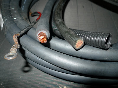
From the left: Original ground cable, chemical resistant AWG 0 cable, normal car audio power cable AWG 0, 16mm conduit.
 How I did it:

1) Strip the cable according to the crimp length.


2) Slip in the crimp and the conduit.


Crimp it using the crimper. 
Or u can use a hammer and thick nail to dent in the crimper. It will be helpful if u hold the crimp in place with the electrical tape before hammering away.  

Another thing to note is to make sure your crimp are in the correct orientation as it is almost impossible to twist the thick cable in place for the bolting points if u have it in the wrong direction. 

Do a trial fitting in the car before crimping. Eg. my crimps are flipped differently for my installed ground cable.
You may solder the wire to held it better to the crimp. As for my case, the wires are too packed for the solder to flow through and the wires are held very tightly using the crimper.


3) Slip on the rubber boot (this is for looks only)


4) Slip over the heat shrink (Adding the heat shrink is to prevent moisture or fumes going into the conduit.) I used the hot air gun to shrink it, alternatively u can try using hair dryer or just plain lighter to heat up the heat shrink.


Old vs New


Complete ... for one point ;p

The cost of making a overkill high quality 5 point grounding kit is less than $100.
You may choose to go without the conduit, rubber boot and the heatshrink cutting the cost further. The reason I had those is to achieve a OEM look.


26 November 2010

OBD1 ECU Plug - Pin Removal

I have recently acquired a Hondata S300 and realised that it can have additional signal inputs (Sensors, secondary fuel map activation, etc).  To have such functions, I had to add additional pins inputs to the ECU plugs. I managed to get a spare ECU plugs for the pins.

I tried to google for instructions on how to do this, but I only manage to find vague answers to it.  For example: insert pin - wiggle pin both ends while pulling to remove pin... So I decided to have this how to when I figured how to remove the pin effectively.

This is one of the EG OBD1 ECU plug. I have removed most of the pins except two of them for this how-to demonstration.


First of all, u have the unhook the 'clamp' at the back of the plug.


Use a small flat screw driver to unhook the catch.


Once u are done, this is how it looks like from the back.


Insert a paper clip from the front to lift up the catch and plug the pin from the back.


This is how the pin is being held in the plug. Insert the paper clip (blue in the diagram) from the front at a angle and feel for the catch (black) , lift it up and u will be able to remove the pin easily.

Thanx to Amos again for the spare OBD1 ECU plugs :).

21 November 2010

Imported new and used parts from Japan.

So far I have gotten quite a bit of replacement parts from a friend who brings in half-cuts from Japan, there are stuffs like complete wiring harness for engine and under the dash, the EK9 handbrakes and DC2R Air Filter box with piping which are in very good condition.  I have been very happy with the quality of items and the best thing is that he is knowledgeable EG6 owner too!

At the same time I understand items like these are hard to source for, so if anyone is interested in getting some stuff (used or brand new) for your EG/EK/DC2 etc, just email Amos at 99@universalexports.sg directly instead of emailing me ;p.

Skunk2 Camber Kits and Rear Lower Control Arm

Finally got to install my camber kit and rear lower control arm today.  Anyway, I got the camber kits to adjust the uneven camber all round due the lowering of the ride (coil-overs).  There are a few things I want to share with those who are looking to install their camber kit.

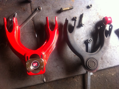
The one on the left is the Skunk2 camber kit and on the right is oem front upper control arm.  The red bushing next to the oem front control arm is the Energy bushing for the arm.
This the camber kit/front upper control arm with the ball joint installed. This is for reference purposes.
The OEM bushing has cracked.  (One month lead time to order  the oem replacement parts from the local agent)
Here is the ball joint with Energy bushing installed. (Thanx to Melvin, for the bushings!)


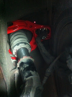
Front camber kit installed


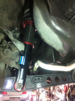
Shown here is the rear Lower Control Arm installed.
(I noticed my anti-roll bar link bushing has worn off, = off I go to the local agent)


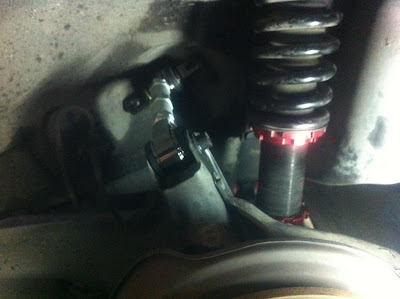
Rear Camber kit installed


Done! Personally I like the Skunk2 rear camber kit as it is very well built, so is the rear LCA which has very good machining design.

Stuff to get before going to the workshop to have your camber kit or Rear LCA.installed:
1) Replacement bushing - do order a set of bushing before install your camber kits, make use of the chance to replace all the worn bushing. Especially the front upper arm and rear anti-roll bar link bushing. It will take about a month time if u order from the local agent. Alternatively, you make use of this chance to replace them with Energy bushing. Of course, do check if the workshop u are going to is able/willing to replace the bushings for u.

2) Do check your rear coil-overs or suspension if it is for EK or EG.  This will determine which LCA to get.


15 November 2010

Throttle Cable Swap - EG to EK

This for those looking have neater engine bay or going to change their 'rough' throttle cable for their EGs.

As the original EG throttle cables (RHD) routes from the firewall to the front of the engine and round back to the throttle body makes it looks a bit unsightly and sometimes gets in the way when working on the engine.  The solution is to get the EK throttle cable (part no. 17910-S04-Q06) which is shorter and routes thru the back of the intake manifold making the engine bay looks a bit tidier.

Before

After

 How-to:
Step 1: Loosen nut A.
Step 2: Turn the throttle to max position so that the cable can be remove by moving the un-thread area near nut A thru the slot at the retainer.


Step 3: Once the cable is loose, unhook the end at the throttle.


Step 4: At the top of the gas paddle (Under the dash), unclip the other end of the throttle cable.


Step 5: In the engine bay, next to the master brake cylinder is where the throttle cable exit is. Twist the cable clockwise till the protruding part is facing the top and u will be able to remove the cable from the firewall.


Step 6: Install the EK throttle cable in the reverse order. 

Note 1: First adjust nut B position, so that the cable near the throttle body is not too taut. If not, the throttle will not be able to close fully. Once that is done, tighten nut A.

Note 2: I am using a Type-R intake manifold and no modification to the cable retainer position is required. I am not sure if modification is required for other types of intake manifold.


07 November 2010

PLX SM-AFR installation (quick run-thru)

Did the installation of the SM-AFR today. It is actually very simple. All u need is just to get a switched (ACC 12v) power source and a ground to power up it up.


I was lucky that a bung was already on the exhaust piping, thus saving me the trouble to get another bung welded to the piping. Therefore it just screwing the O2 sensor and route the harness thru the chasis.

This is the power supply wiring the SM-AFR. Simply just tap the red wire to the switched power source (12v at position II at the key switch) and the black to ground.


A TIP - There are 5 unused slots at the fuse box under the dash. (See where the black and yellow wires with the blue crimp?)  It is numbered 5 - 4 - 1 - 2 -3 from the left.

5 - Constant 12v
4 - Constant 12v
1 - 12v when key is at position II
2 - 12v when headlights are switch on
3 - 12v when key is at position I

I used the source from slot 1 (third from the left) for the power supply the SM-AFR.

After that is done, its pretty much just plug everything into the sensor module :) and u are good to go.

05 November 2010

PLX SM-AFR with DM-5

I am suspecting that my engine is running slightly rich, which lead to me deciding between the PLX and Innovate AFR.

Innovate was presented as more programmable and easier interface for datalogging, while PLX was recommended by HONDATA but its more expensive ( which I intend to use for tuning the car). After going thru tons of forum and feedbacks, PLX seems to be more gentle on the O2 sensor compared to Innovate (Both use the same sensor, but somehow Innovate has more reports on dead O2 sensor within 2 years). 

Therefore I got myself the PLX for the reliability and for trying to conform to what HONDATA recommended.

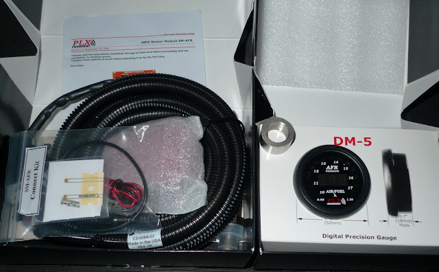
In the Box


SM-AFR with DM-5 display
Got this from E-Bay, it came with a free exhuast bung for the O2 sensor.


The harness that was included was robust and the wires are well conduit. Good quality stuff.

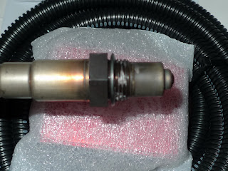
Lithium grease was applied by the manufacturer around the thread of the O2 sensor which is a nice touch. 

I will update on the installation again later. 

I will not be able to provide any comments on accuracy as I will not be able to do a comparison.

01 November 2010

Manual Steering Conversion

I was under the impression that in order to get rid of the power steering (possibility of leaks, leaks & more leaks) that I have to find a manual steering rack. However, thanx to a friend who point out to me that there is a easier way over at Honda-tech forum, which is to reroute the hydraulic pipes and add a breather tank. I will be doing this conversion the next time my steering pump or piping gives way again. 

Took this pic from Honda Tuning Website (Fantastic Magazine). U get the idea on how to do this. 
(Just type in power steering and u can find the article on a ready kit)